Clipper Architecture: Cropping a Drawing Out of a Crowded CAD File.
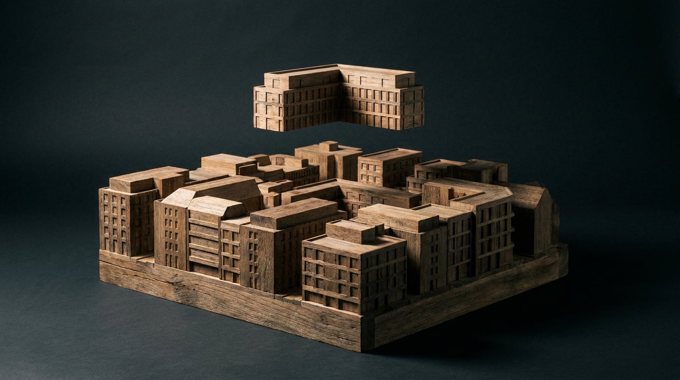
One practice CAD file can hold twenty drawings on the same layers. Here is how architects crop a single plan clean out of it, in Vector and in Linea.
What Clipper Architecture Means in Day-to-Day Practice
 Clipper architecture is the craft of showing only the part of a drawing that sits inside a boundary, and hiding or discarding everything outside it. In practice you meet it in two places. One is the cropped viewport on a sheet. The other is the clipped polyline, where a line is cut cleanly at the edge of a window or frame rather than running on beyond it.
There is a second reading, and it is worth settling now. In computer graphics, clipping also means cutting linework at the edge of a shape. That is the machinery under the hood. This article is about the practice-level job: **cropping one drawing out of a crowded CAD file**, so that what leaves your hands is a single clean plan, section or elevation and not the whole model space.
The trigger is mundane. A practice CAD file routinely holds twenty-odd drawings in one model space: the ground floor plan, the first floor, two sections, a door schedule, a handful of construction details, an old site plan nobody deleted. A planning consultant asks for the ground floor plan. A structural engineer wants the first floor. A client wants to see one elevation. Nobody wants the whole file, and you cannot send it anyway, because it contains drawings you have not finished, notes to yourself and, occasionally, a consultant's information you were not meant to forward.
For a small practice the cost lands on the clock. Redrawing the plan by hand wastes a morning. Deleting everything else by hand takes nearly as long and leaves debris. Cropping properly takes minutes, and the method barely changes with the situation:
- A studio inheriting an old file needs one plan out of a predecessor's tangle, with layers it did not name.
- A student preparing a portfolio plate needs one section lifted from a studio drawing that also holds three classmates' worth of crit scribbles.
- A visualiser lifting one elevation needs clean linework to sit under a render, without the plan, section and title block attached.
The goal is not to delete a model space down to one drawing. It is to isolate the drawing you need before it lands, so nothing stray comes with it.
Why Layer Filters Fail When Twenty Drawings Share One Layer Set
 The usual first move is the layer picker. You open the layer manager, untick what you do not want, and expect the plan to stand alone. It does not work, and the reason is structural.
Practice files organise by building element, not by drawing. Walls live on a walls layer, doors on a doors layer, dimensions on a dimensions layer. The ground floor plan, the first floor plan, both sections and the details all draw their walls on that same walls layer. Ticking layers can switch walls on or off for every drawing at once. It cannot separate one drawing's walls from another's, because nothing in the layer set knows where one drawing ends and the next begins.
### The workaround, and where it breaks
So people fall back on the manual route: hide the obvious layers, select a window around the unwanted drawings, delete, repeat. It works well enough to tempt you and badly enough to cost you:
- Stray linework. A dimension string from the neighbouring section survives because it sat on a layer you needed for your own plan.
- Xrefs. Externally referenced files are easy to leave attached, and they drag the consultant's backgrounds into the file you are about to send.
- Title-block fragments. Corners of a frame or a stray revision cloud sit just outside the selection window and slip through.
- Dirty geometry. The deleted drawing may have shared entities with the one you kept, leaving gaps you only notice on the plot.
Layers sort by element. Cropping sorts by drawing. When twenty drawings share one layer set, only the second one can pick out a single plan.
Cropping a Single Plan Into Vector, Step by Step
 Here is the workflow from file to clean plan. Nothing in it needs a redraw.
### 1. Open Import and read the report
Open Vector and start from Import. Drop your DWG, DXF or vector-ready PDF. For a DWG, the file is converted on the server and the upload is removed afterwards. The pre-import report appears before anything is created: it draws the document that is about to exist, lets you tick which layers to keep, and outlines each separate drawing it has found.
### 2. Click a region to crop to it
Click one of the outlined regions and the import crops to that one drawing. The outlines are reachable by keyboard as well as by pointer, which matters if you work without a mouse or on a laptop trackpad you do not trust. What sits outside the box does not vanish abruptly: it dims, so you can see what you are leaving behind and confirm the box has caught the right thing.
### 3. Where detection fails, drag your own box
Automatic detection can find nothing, or get it wrong. A plan may be drawn without a clear frame, or two drawings may touch, so the region you want is not outlined cleanly. Drag your own box on the preview and it does the same job. Linework crossing the box is cut clean at the edge, and the sheet is resized to the box. This is the clipper idea in its plainest form: a boundary, and a clean cut where lines meet it.
### 4. Confirm units and check scale
On a DWG or DXF the file's own units are confirmed, and you can override them if they are undeclared. The drawing then lands at true 1:1 real-world scale automatically. A PDF is different: it states a page, not a scale, so you set the drawing's real-world scale yourself by picking a standard metric or imperial ratio, or by calibrating against a known distance.
Then check it. Use the Measure tool: click two points for a distance, or hover a closed shape for its area and perimeter. Measurements read in real units once a scale exists, and in paper millimetres, clearly flagged, until then. A true scale bar regenerates automatically whenever the scale changes, so you do not rebuild it by hand.
| Source file | What lands | Scale |
|---|---|---|
| DWG or DXF | The file's own real layers, as-is | True 1:1 real-world scale, automatically; units confirmed or overridden if undeclared |
| Vector-ready PDF | Editable linework, layers restored from the PDF's own optional content groups or, failing that, colour and lineweight | You set it: standard ratio or calibrate against a known distance |
Read the report, click one outline, check the scale. If detection misses, drag your own box. The cut is clean either way.
Clipping Masks: Cropping Without Deleting Anything
Cropping at import is destructive in the useful sense: you decide what to keep and the rest is gone. Sometimes you want the opposite. You have a whole imported sheet on an artboard, you want only one elevation visible, and you want the rest still there underneath in case the client changes their mind. That is what a clipping mask is for. ### How it works Select two or more objects, or one group. The topmost object becomes the mask, and everything beneath it shows only inside that shape. It is the digital version of laying a window cut from card over a printed sheet, and the same idea as the clipped viewport on a layout. The rules are worth stating plainly, because they catch people out:- The mask has to be a single path. A compound shape or several loose paths will not do.
- The mask loses its fill and stroke when it becomes a mask. It is a boundary, not a drawn object.
- Releasing it hands the object back unpainted. The geometry returns exactly as it was, but without the fill and stroke it had before.
| Situation | Better route |
|---|---|
| You will never need the rest of the file | Crop at import |
| You may want to reframe later | Clipping mask |
| Drawing too large for the document size cap | Crop at import |
| Several views from one source on separate boards | Clipping masks, one per artboard |
Crop first when the rest of the file is dead weight. Mask when you want the option to change your mind without redrawing.
Taking the Cropped Plan Into Linea, Layout and Retouch
A cropped plan is rarely the end of the job. It tends to move on to a model, a board or a render, and the same cropping logic carries across the suite. ### Linea does the same job for a model Linea is the BIM authoring tool in the browser, where the plan and the 3D model of the same building are edited together. Its import dialog works like Vector's: it draws the file before it lands and finds the separate drawings inside it. A click on an outlined region, or a box you drag by hand, crops the import to the single plan you wanted. It arrives cut clean at the edge and lands on the origin, ready to be built on. Linea imports DWG, DXF and IFC, with IFC taking native files from Revit or ArchiCAD, so the same trick works whichever package the original came from. ### The round trip The two studios hand work to each other both ways. Linea's DXF export carries an Open in Vector action, which creates a new Vector document directly. Vector's DXF export panel carries an Open in Linea action, which creates a new, empty Linea model ready to import the file. That gives you a practical loop: crop a plan in Vector, tidy and annotate it, send it to Linea to build the model on top, export a section back out and finish it as a board. ### Setting it on a sheet For a crit board or competition panel, set the cropped plan in Layout, the sheet-and-document tool in ArchAdemia Tools. Its Sheet mode is one large surface, A1 landscape by default, with a toggleable layout grid and guides that elements snap to. Export a vector multi-page PDF at true sheet dimensions, with optional bleed and crop marks if the board is going to print. Alternatively, if the plan is staying in Vector, export the drawing as PDF, SVG, DWG, DXF or PNG; DWG and DXF carry real CAD linework at true real-world scale once a scale is set, without fills, gradients or images. ### When the plan is a photograph or a scan Sometimes the source is not CAD at all: a photographed site sketch, a scanned 1960s plan, a client's printed floor layout. Image Trace in Vector turns a placed photograph into editable paths. The linework lands on top of the photograph at exactly its size and position, as its own new layer, and the photograph is hidden rather than deleted. It needs a PNG, JPEG or WebP under 5MB, it uses plan credits, and the cost is shown before it runs. For a faint or skewed scan, Retouch is the place to correct the photograph first, with its Crop tool, a Camera Raw style Adjust panel and perspective distortion of a layer by dragging its corners, so the trace has cleaner contrast to work from. ### The order of operations The sequence that keeps files light and drawings honest is short:- Crop first. Isolate the one drawing you need, at import if you can, with a clipping mask if you want the option to change your mind.
- Tidy second. Accept the real fills worth keeping, rejoin the broken polylines and remove the duplicates.
- Set the scale last. Confirm the units on a DWG or DXF, calibrate a PDF against a known distance, and check with the Measure tool.
Crop first, then tidy, then set the scale. Reversing the order means cleaning up drawings you were never going to send.
Keep reading.
Try ArchAdemia Tools for yourself
Draw it, model it, render it, publish it. One place, built for architects and small practices. From £19 a month, all in.