From Concept Sketch to Submitted Drawings: A Planning Workflow.
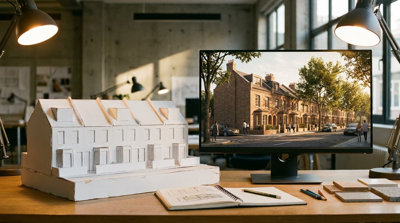
A working sequence from first massing sketch to a submission-ready drawing set, using one project across sketching, modelling, rendering and the DAS.
Why most planning workflows break somewhere in the middle
Most planning applications don't fail because of bad design. They fail, or get held up, because the submission doesn't hang together: a concept sketch that never got traced into anything measurable, a render built from a different model than the one issued for planning, drawings at the wrong scale, or a Design and Access Statement that describes a scheme slightly different from the one in the plans. None of these are design problems. They're workflow problems.
The first failure point is the sketch itself. An architect draws a promising option on paper or a tablet, the client likes it, and then it sits as a scanned image while someone else starts modelling "something like that" from scratch in CAD. The trace is approximate. The model and the sketch diverge from day one, and every downstream drawing inherits that gap.
The second failure point shows up later, closer to submission. Someone exports a view from the working model, opens it in a separate rendering tool, adjusts the camera, swaps a material, and produces a beautiful image that no longer matches the linework in the drawing set. A planning officer comparing the render to the elevation notices the discrepancy immediately. Local authority validation checklists are unforgiving about this: they expect scaled drawings, consistent visuals, and a narrative that doesn't contradict either.
The fix isn't a better render or a more careful sketch. It's treating the whole sequence, sketch, trace, model, drawing set, statement, as one continuous file rather than five disconnected tools stitched together at the end. This article walks through that sequence in six stages, using a small residential extension as the running example: a rear ground-floor extension with a new first-floor room over it, on a suburban plot with close neighbours on both sides.
A planning submission rarely fails on design quality. It fails when the sketch, the model, the drawings and the statement stop agreeing with each other somewhere along the way.
Stage 1: Turning a hand sketch into a working base

Start with the sketch as it exists, whether that's a napkin drawing, a marked-up survey, or a tablet sketch from a site visit. Photograph or scan it and bring it into Linea as a trace guide. This happens on desktop, where the calibration step needs a proper viewport and mouse precision rather than a touchscreen.
Before anything gets traced, set a real-world length against a known dimension in the sketch, a door width, a boundary line, a dimension already noted on the drawing. This calibrates the whole image so that tracing produces accurate geometry rather than a scaled guess. Skip this step and every wall you trace afterwards inherits the same small error, compounding across the plan.
Tracing is the one AI-assisted build step worth using here. Linea turns the calibrated sketch into real walls, not a generic "build my model" shortcut that guesses at a design. It's closer to an assistant with a straightedge than a design generator: it follows what's already been drawn and produces parametric geometry from it. That distinction matters for a planning workflow, because the walls that come out of the trace need to be the walls that get submitted, not a reinterpretation.
Once the footprint exists, place it on its real site location with surrounding context and ground. For the extension example, that means the neighbouring gable ends, the boundary fences, and the existing house massing all sit in the model from the first sketch onward. Massing decisions made in the next stage respond to actual neighbours rather than an assumed empty plot.
Calibrate before you trace. A trace built on an uncalibrated sketch looks right and measures wrong, and that error follows the project through every later drawing.
Stage 2: Massing and testing options before committing to detail
With a calibrated footprint sitting in real context, switch into Massing to block out two or three volume options as real solids, using push/pull rather than committing to walls and openings too early. For the extension, that might mean testing a flat-roof single-storey option against a pitched-roof two-storey option, both as simple blocks first.
The pickable face graph lets you test roof pitches, set-backs and storey heights directly against the neighbouring context already placed in the model. Push a roof plane up and check it against the neighbour's eaves line. Pull a first-floor wall back from the boundary and see the set-back register against the fence line in three dimensions, not as a dimension string on a 2D plan that someone has to interpret.
Group blocks to hide early scaffolding without losing it. A discarded flat-roof option doesn't need deleting: group it, hide it, and it stays available if a client or planning pre-application conversation swings back towards it later. This keeps two or three live options open for a design review rather than forcing a premature decision.
Once a massing option is agreed, whether that's the client signing off in a meeting or a design review settling on a direction, move into Build. Add parametric walls, doors, windows, roofs and stairs to the chosen volume. The massing block becomes the shell that the detailed model fills in, rather than a separate sketch model that gets thrown away and rebuilt.
Testing three massing options as solids against real neighbouring context takes an afternoon. Redrawing three separate detailed models to compare the same options takes a week.
Stage 3: Producing the drawing set from the same model

Cut plans, sections and elevations directly from the 3D model as real linework. This is the point where the "same file" principle pays off: because the drawing set is cut from the model that was traced from the sketch and refined through massing, there's no separate drawing exercise that can drift from the design decisions made earlier.
Save views so they can be reissued automatically after a late client change. If the client asks for the first-floor window to move 300mm during a pre-application conversation, that change happens once in the model. The saved plan, section and elevation views update rather than needing manual redrawing across every sheet that referenced the old window position.
Export the sheet as a PDF at a true plotted scale on the correct paper size, with a title block, ready for a planning portal upload. Local authority validation checklists commonly specify true scale, 1:50 or 1:100 depending on drawing type, on A3 or A1 paper. A PDF that isn't plotted at true scale is one of the most common reasons a submission gets kicked back at validation before an officer even looks at the design.
Where a consultant or the local authority needs the drawings in a CAD-native format, export DXF. Where the project already has a Revit or ArchiCAD model to build from, for instance where a structural engineer has produced an existing IFC model of the house being extended, import that IFC directly rather than re-tracing from paper.
Comparing the two paths into a working model
| Starting point | Route into Linea | Best use case |
|---|---|---|
| Hand or tablet sketch | Photograph, calibrate, trace into walls | New concept designs, early-stage extensions |
| Existing Revit/ArchiCAD model | IFC import | Working from a consultant's existing model or a listed building survey |
| CAD drawing from a third party | DXF import/export | Coordinating with structural engineers or other consultants mid-project |
Stage 4: Contextual visuals that support the application, not decorate it
Planning visuals have a different job than marketing renders. They need to show the officer and any objecting neighbours what the scheme actually looks like from the angles that matter, not the most flattering angle available. Send a perspective view straight from Linea into the rendering studio so the render matches the submitted model exactly, camera position, massing, openings, all inherited from the same geometry that went into the drawing set.
Use Shoot to generate a consistent set of exterior angles: the street view that shows how the extension reads from the public realm, the garden view that shows the scale relative to neighbouring gardens, and the angle that answers the planning officer's likely objection, often the view from the neighbour's rear window towards the new first-floor addition.
Apply a re-light preset such as Overcast for a neutral, factual daylight read. A golden hour render looks good on a competition board but reads as evasive in a planning context, where officers and objectors are looking for an honest representation of massing and shadow, not a dramatic lighting moment. Overcast strips that ambiguity out.
If a render comes back with a soft or repetitive area, a brick elevation that's lost detail at a distance, or a roof material that's rendered flat, use Retouch's enhance area tool to re-render that region at higher resolution without touching the rest of the image, or use material swap to correct a texture against a reference before the image goes into the statement. Both operations land on a new layer, non-destructively, so the underlying render stays intact if the correction needs revisiting.
A render generated from the same model that produced the drawings can't contradict those drawings. A render generated separately, however carefully matched by eye, always risks it.
Stage 5: Assembling the Design and Access Statement

Build the Design and Access Statement in Layout using the Design and Access Statement template, structured as an A3 Document rather than a single sheet. This matters more than it sounds: a DAS is a multi-page narrative document, not a poster, and treating it as a Document from the start means pages reorder and duplicate cleanly as the statement grows.
Pull in the plans, sections, elevations and contextual renders produced in the earlier stages. Because every image traces back to the same underlying model, whatever gets swapped into the statement stays consistent with what's in the drawing set and what a planning officer will see in the visuals folder.
Ask Corb to draft or tighten specific text frames rather than the whole document at once, the access statement section, the design rationale, the response to a particular local policy. Select the frame and choose the model that suits the section: Sonnet for a balanced, policy-literate draft; Opus for a section that needs deeper reasoning, such as justifying a design decision against a conflicting local plan policy; and a more narrative-oriented model where the writing needs to read well to a lay reader, such as the introduction a neighbour or objector might actually read in full.
A DAS doesn't need to be written from a blank page every time. It needs specific sections tightened against specific requirements, and different sections often call for a different kind of writing.
Export the finished statement as a vector PDF at true page size for the planning portal upload, or share it as a read-only link where a pre-application conversation with planning officers calls for something they can review online before a formal submission goes in.
Stage 6: Final checks before the file goes in
Before anything uploads, cross-check that every drawing scale matches what the local authority's validation checklist actually requires. Requirements vary by authority and by drawing type, existing and proposed plans at 1:50 or 1:100, location plans at 1:1250 or 1:2500, and a submission with the wrong scale on even one sheet risks invalidation regardless of design quality.
Confirm the render set and the drawing set show the same massing, materials and openings, with no late-stage drift. This is the moment to catch the gap that opened this article: a window that moved in the model after the renders were generated, or a roof pitch adjusted in Massing after the perspective view was already sent to Shoot.
Reissue any saved view affected by a last-minute design change rather than manually redrawing it. If the client asks for one more adjustment the night before submission, a saved view in Linea updates automatically once the model changes, rather than requiring someone to redraw a section by hand under time pressure.
Keep the working file live after submission. Amendments during determination, and most applications get at least one round of officer comments requesting a minor change, are far faster from an already-set-up model with saved views and a linked drawing set than starting again from a flattened PDF export.
The submission isn't the end of the model's working life. Officer comments and conditions almost always mean going back into it, and a live model handles that in minutes rather than days.
The takeaway
A planning submission holds together when it comes from one continuous chain rather than five separate tools bolted together at the deadline: a calibrated trace, a tested massing option, a drawing set cut from that same model, visuals rendered from the same geometry, and a statement that pulls all of it in without re-describing a different scheme. Keep the working file live through determination, and the inevitable round of officer queries becomes an update, not a rebuild.
Keep reading.

Try ArchAdemia Tools for yourself
Draw it, model it, render it, publish it. One place, built for architects and small practices. Plans from £29 a month, all in.