Building a Consistent View Set for a Planning Submission.
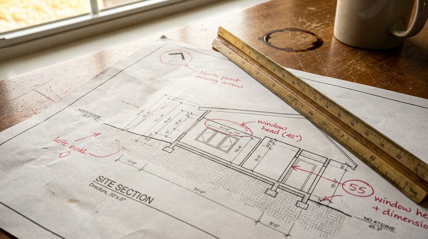
Planning officers spot inconsistency fast. Here's how to keep plans, sections and elevations reading as one coherent set from first sheet to last.
Why planning officers notice inconsistency before they notice design
Planning officers read fast and they read defensively. Before they form a view on massing or materials, they scan the submission for coherence: is the north point the same on every drawing, does the scale convention hold across the set, does the drawing hierarchy make sense sheet to sheet. That scan happens in the first few minutes, and it decides whether the rest of the submission gets read with trust or read with suspicion.
This is not a stylistic preference. Planning guidance in multiple jurisdictions is explicit that submissions need clear titles, accurate scales, north points, section lines and revision references, precisely because officers are cross-referencing drawings against each other to check the story holds together. A site plan at 1:200 next to an elevation quietly drawn at 1:100 is not just untidy, it is a discrepancy the officer now has to resolve before they can trust anything else in the pack.
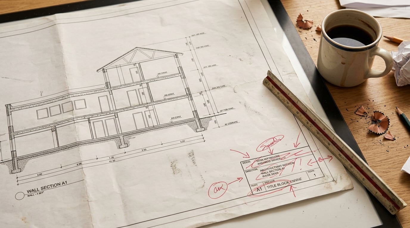
Inconsistent line weights between a plan and its matching section read the same way. If the plan shows a wall as a heavy poché but the section cuts through the same wall with a thin outline, the officer does not conclude "different drafting style." They conclude the drawings may not describe the same building, and that suspicion colours everything downstream. The specific failure points worth naming: elevations drawn at a different scale to the plans they relate to, section cuts that do not align with what the plan actually shows, and drawing titles that use different terminology for the same element across sheets.
A submission that reads as internally consistent gets processed faster and queried less, because the officer is not spending their attention re-verifying basic facts. That is the entire commercial case for tightening a view set before submission: less back-and-forth, fewer requests for clarification, faster committee dates.
An officer's first pass through a submission is a coherence check, not a design review. Fail that check and the design review starts from a position of doubt.
Start from one model, not five separate drawings

The most reliable way to guarantee a plan, section and elevation describe the same building is to stop drawing them separately. In Linea, plans, sections and elevations can all be cut from the same 3D model rather than redrawn by hand for each sheet. That geometric link is what keeps a submission honest: if the section doesn't match the plan, it is because the model itself is wrong, not because two drawings drifted apart during production.
Linea issues cut sections and elevations as real linework onto a sheet, the same way it issues a plan, at a true plotted scale with a title block. That matters for planning submissions specifically, because officers and third parties sometimes measure directly off a printed or PDF drawing. A section that is genuinely plotted at 1:50, rather than a screenshot scaled to roughly look right, holds up to that scrutiny.
The other practical advantage is what happens after the first submission goes in. Planning officers routinely come back with a request: move a window, adjust a datum, revise a boundary treatment. In a traditional 2D workflow, that change has to be manually chased through every affected drawing, plan, section, elevation, each one redrawn or adjusted by hand, with every redraw a fresh opportunity for the set to drift out of alignment again. In Linea, saved views can be reissued after the model changes, so a single edit to the massing propagates through every view drawn from it. The revision cycle gets shorter and the risk of one sheet quietly falling out of step with the rest drops close to zero.
One model driving every view is the single biggest lever for consistency. It removes the manual re-checking step entirely, because there is nothing to re-check: the geometry cannot disagree with itself.
Fix your conventions before you draw a single sheet
Consistency is a decision made once, at the start, not a cleanup pass at the end. Before producing a single view for the submission, settle three things and hold them across the whole set.
Scale per drawing type. Site plans typically sit at 1:100 or 1:200, floor plans at 1:50, details at 1:20. Pick the convention for the project and do not deviate sheet to sheet, even when a smaller building tempts you to bump a floor plan up to 1:100 to fill the sheet better. A mixed-scale set is one of the fastest ways to make an officer distrust the rest of the drawings.
Line weight and hatch conventions. Cut elements should read heavier than elevational lines throughout the set, and poché for solid versus void should be applied the same way on every plan and section. Set this once as a standard and apply it everywhere, rather than adjusting it per sheet based on how a particular drawing happens to look.
North point, key plan and numbering. Decide the drawing numbering system and the key plan format before producing views, not after. Retrofitting a numbering convention onto a set that is already half-drawn is where inconsistencies creep in, because early sheets get renumbered under time pressure and something gets missed.
Placing the scheme on a real location with surrounding context, which Linea supports directly, keeps site plans and context elevations reading against the same ground plane. This matters more than it sounds: an officer assessing relationship to neighbours is comparing your proposed massing against real adjacent buildings, and if the site plan and the context elevation were modelled against different assumptions about ground level or neighbouring roof heights, the visual story falls apart on comparison.
| Drawing type | Typical scale | Consistency risk if unfixed |
|---|---|---|
| Site plan | 1:100 or 1:200 | Context buildings misrepresented against neighbours |
| Floor plans | 1:50 | Room dimensions read differently sheet to sheet |
| Sections / elevations | Matched to plan scale | Section doesn't align with plan it's cut from |
| Details | 1:20 | Construction logic contradicts the section |
Fix scale, line weight and numbering before the first sheet is drawn. Retrofitting conventions onto a half-finished set is where inconsistencies get missed under deadline pressure.
Building the sheet set in Layout

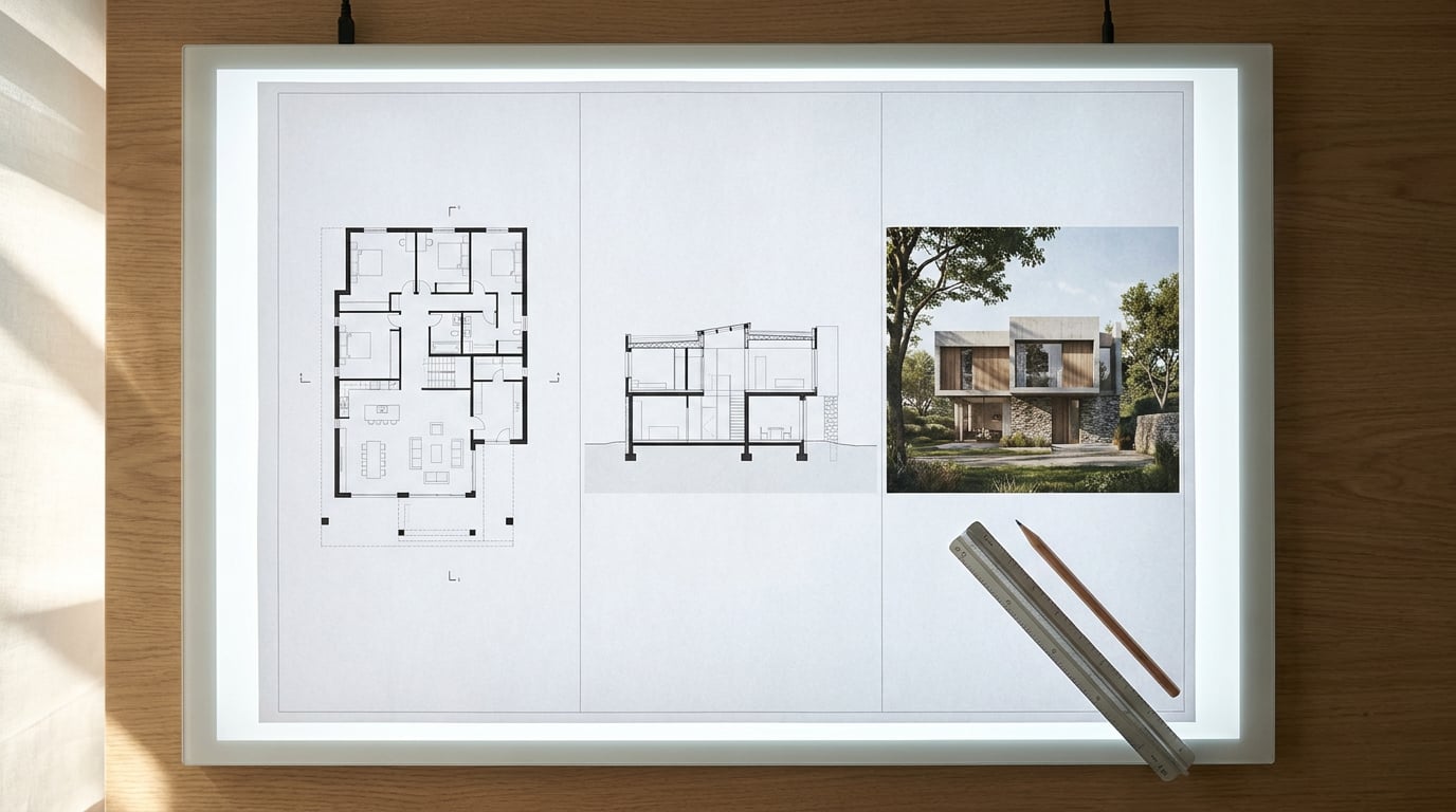
Once the individual drawings are consistent, the sheet set itself needs to read as one document. Layout's Document mode is built for exactly this: a multi-page Design and Access Statement, with plans, sections and elevations held in a fixed page order at A3, rather than a loose collection of exported images assembled at the last minute.
A toggleable layout grid, in Manuscript, Columns or Modular arrangements, keeps image frames and text blocks aligned across every page without eyeballing it. This is a bigger deal on a planning set than it sounds: a DAS with fifteen or twenty pages is easy to let drift, where the caption sits slightly higher on page 6 than it does on page 12. The grid removes that judgement call entirely, because every element snaps to the same reference lines throughout the document.
Type consistency matters just as much as layout consistency. Layout offers an eight-family library, Helvetica Now, Inter, IBM Plex Sans and Mono, Archivo Narrow, EB Garamond, Instrument Serif and Space Grotesk. Pick one family for the whole submission, drawing titles, scale bars, captions, and hold it across every page. Mixing fonts sheet to sheet is a small thing individually but it accumulates into the same signal as inconsistent line weights: it tells the reader the document was assembled in pieces rather than produced as a coordinated set.
Export as a multi-page PDF at true sheet dimensions. This is not a cosmetic detail. The exported PDF places each page as a high-resolution image at exact millimetre dimensions, which means the geometry stays true when an officer prints the set or scales off a drawing on screen. A scale bar that reads correctly on screen but drifts on a printed A3 sheet undermines the whole submission, regardless of how well the design itself is resolved.
A DAS that looks like one document rather than a stitched-together export earns faster, more trusting reads. Grid alignment and one type family do more for perceived professionalism than most people expect.
The small decisions that make a set read as one document

The last mile of consistency is in the details most people treat as an afterthought.
- Title block positioning. Keep drawing titles, scale statements and revision references in the same position on every sheet, not just in the same visual style. If the title sits bottom-right on sheet three and top-left on sheet seven, the officer has to relearn where to look every time they turn a page.
- Matching annotation wording. If a section calls out a finished floor level as "FFL +2.400", the plan referencing that same level needs to use identical wording, not a rephrased version. Small inconsistencies in terminology read as small inconsistencies in the design itself, even when they are purely a labelling choice.
- A consistent key plan thumbnail. Use the same small key plan on every sheet so the officer never has to hunt for orientation before they can read the drawing. This single repeated element does more for navigability than almost anything else in the set.
- A final pass across the whole exported PDF. Before submission, check that no sheet drifted in scale, font or line weight while others were being revised individually. Revision cycles are exactly where inconsistency creeps back in: sheet four gets updated for the officer's comments, sheet nine doesn't, and the set is out of alignment again without anyone noticing until it's queried.
Toronto's own guidance for 3D context views is unusually specific about exactly this kind of reproducibility: applicants should submit at least two 3D model views from opposite corners of the site, using the same camera height and distance in both images, exported at a minimum height of 3200 pixels. The rule of thumb given is camera height at roughly 1.5 times the building height and camera distance at roughly 4 times the building height. The document also notes that the same 3D massing model can be used to generate multiple submission graphics, which is the same logic as cutting every 2D view from one model in Linea: consistency is achieved by reusing a single source, not by matching separate outputs after the fact.
Hong Kong's planning guideline pushes the same principle further, requiring viewpoint maps and photomontages with the exact camera position, height, angle and focal length documented for every graphic submitted. That level of specificity exists because visual impact assessment depends on being able to compare views like for like. An officer cannot judge whether a proposal overshadows a neighbour if the "before" and "after" images were shot from different positions or different lens angles. UK-facing planning guidance for renders makes a related point: label each view with its location, direction and date, and include a key plan showing where every viewpoint sits.
Planning authorities are not asking for beautiful drawings. They are asking for reproducible, comparable evidence that lets an officer trust what they're looking at.
The thread running through all of this, whether it's a UK site plan, a Toronto context view or a Hong Kong photomontage, is the same: officers are being asked, and are asking applicants, to treat a submission as one coordinated system of views rather than a folder of separate images. That is close to how architecture theory itself frames the problem: select the stakeholders and their concerns first, then define the viewpoints that answer those concerns, and only then generate the views. A planning set built that way, rather than assembled sheet by sheet under deadline pressure, is the one that reads fastest and gets queried least.
Takeaway
A planning submission is judged on whether it holds together before it is judged on the scheme itself. Fix scale, line weight, north point and numbering conventions before drawing a single sheet. Cut every plan, section and elevation from one model rather than five separate drawings, so nothing can drift between them. Build the sheet set in a tool that holds grid alignment and typography across every page, and export at true dimensions so the geometry survives printing and on-screen measurement. Do that, and the officer spends their first read on the design, not on working out whether the drawings agree with each other.
Keep reading.

Try ArchAdemia Tools for yourself
Draw it, model it, render it, publish it. One place, built for architects and small practices. Plans from £29 a month, all in.