How to Draw the Terrain So the Scheme Sits on a Real Site.
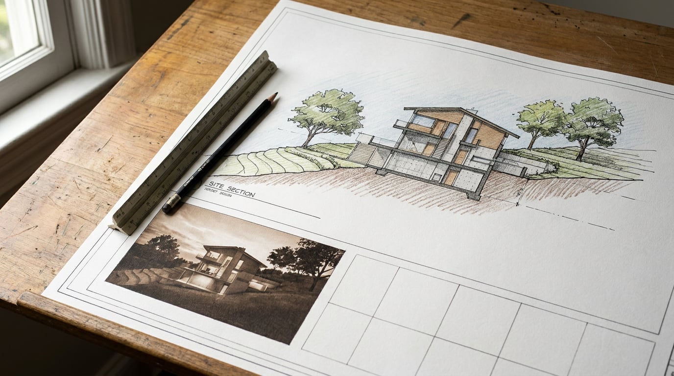
A flat ground plane is the quickest way to make a good scheme look unbuilt. Here is how to draw the terrain so the building sits on a site, not a slab.
Why a flat ground plane gives the game away
 A building on a perfectly level slab looks like a massing study. A building on a site looks like a proposal. Planning officers, clients and crit panels read the ground first, before they read the facade, the materials or the plan. If the ground is a grey rectangle, the scheme has not yet been tested against the place it is meant to occupy.
Three things go wrong on flat ground, and they compound.
- Levels at the threshold stop making sense. A front door needs a reason to be at a particular height. On a flat plane every door is simply "at zero", and the questions a real site forces (step-free access, flood level, the relationship to the pavement) never get asked.
- Retaining walls and steps have nothing to resolve. These elements exist because the ground moves. Remove the movement and you remove the most interesting parts of the scheme: the junctions where architecture meets landscape.
- Sections lose the datum line. A section is a drawing about levels. Without a real ground line, it shows a building floating in white space rather than a building cut into, or lifted out of, a specific piece of earth.
Decide at concept stage whether the ground is part of the scheme's argument. If it is, model it before you design the threshold, not after you write the statement.
Start from the survey, not from a guess
 Before you draw anything, work out what you actually hold. There are three realistic starting points, and each carries a different level of trust.
| What you hold | How far to trust it | What to do |
|---|---|---|
| Topographical survey as DWG or DXF, with spot levels and contours | Measured. This is the strongest evidence you can have. | Import it and model the ground from it. |
| Rough site sketch or printed plan | Indicative only. Useful for layout, not for levels. | Use as a trace guide and flag the ground as provisional. |
| A photograph and an address | Visual impression, nothing more. | Use for context only, and commission a survey before committing to levels. |
- Confirm the units. A survey drawn in millimetres read as metres, or the reverse, is the classic way to produce a building the size of a postage stamp or a small county.
- Confirm true scale. Measure a known distance, such as a boundary length or a road width, and check it against the survey's own dimensions. If it is wrong now, everything built on it will be wrong too.
Separate what was measured from what was inferred, and label the inferred parts as provisional. A confident-looking ground surface is not the same as a surveyed one.
Sculpting the terrain in Linea, and where the building meets it
 Linea includes terrain sculpting alongside parametric walls, slabs and stairs, so the ground and the building live in one model rather than two files you have to reconcile by hand. That is the practical advantage: when the terrain changes, the building sees it.
### Ground first, then the building
Model the ground from the survey contours first, then place the building. Set the ground floor level against the real datum, not against an arbitrary zero, and let the terrain show you where the cut and fill actually fall. This reverses the instinct to draw the building and then "add some landscape". The ground is not a backdrop. It is the first constraint.
### Decide how the building meets the ground
Here is the junction a crit panel or a planning officer will pick at, so decide it deliberately. There are four common answers:
- Plinth. The building sits on a raised base, with the ground falling away around it. Good for flood-prone edges and for giving a modest building presence.
- Undercroft. The ground passes beneath the building on the downhill side. Useful on steep plots, and it keeps the natural fall visible.
- Retained edge. The ground is held back by a wall at the building line. This is a cut-and-fill decision, and the wall height needs to be honest.
- Buried floor. One or more levels sit into the slope. The most efficient use of a steep site, and the one with the most drainage and waterproofing consequences.
Model the ground from the survey first, set the ground floor against the real datum, and choose how the building meets the slope on purpose: plinth, undercroft, retained edge or buried floor.
Drawing the terrain on the sheet: sections, elevations and context
A modelled terrain only helps if it reaches the drawings. The point of working in one model is that the ground line on your section is real linework, cut from the model, not a hand-drawn approximation that drifts when the model moves. ### Cut sections and elevations from the model Cut your sections and elevations directly from the model in Linea. When the terrain changes, the ground line changes with it. This removes the single most common error in site sections: a ground line drawn once, early, and never updated after the levels moved. ### Issue on a sheet at true scale Issue the section on a sheet at a true plotted scale and paper size, with a title block. Then save the view, so you can reissue it after the terrain changes. Saved views are what make a late correction survivable: change the model, reissue the view, and the sheet follows. Export the sheet as a PDF at the plotted scale when it goes out. ### Make the ground line read in Vector Linea's sections can be taken into Vector, the vector drawing tool in ArchAdemia Tools, to tidy the output. Two small decisions make a section read as professional:- Weight the cut ground line. Use the Width tool to make the ground line at the cut heavier than the building below it. Convention is that the thing the section plane actually slices carries the heaviest line, and the ground is the one element the whole drawing hangs from. The Width tool lets a line's weight vary along its length, and a Width profile row offers presets such as Taper in or Swell in the middle in two clicks.
- Tint the ground without losing the linework. Put a tinted fill on the ground and set its blend mode to Multiply. The contour and hatch linework underneath keeps reading through the colour, instead of being buried by it. Multiply is the one an architect wants for exactly this reason.
Cut the ground line from the model, issue it at true scale, save the view, and make the ground the heaviest line on the section.
From terrain to render: carrying the ground into the visual
The render is where the terrain either sells the site or exposes it. The risk is that the visual quietly replaces your modelled ground with a fresh flat plane, or with a generic landscape that matches nothing on the survey. ### Send the view, not a new scene Send a perspective view from Linea straight into the rendering studio. The terrain you modelled is then the terrain the render sees, rather than something re-invented from a prompt. This keeps the slope, the retaining edge and the threshold level consistent between the section and the image, which is exactly the consistency a planning officer will check. ### Brief the ground specifically When you write the render brief, name the ground. Describe the slope, the retaining edge and the planting rather than writing a generic landscape prompt. "A two-metre fall across the plot, a low limestone retaining wall at the building line, rough meadow grass above and gravel below" gives the model something to hold on to. "Nice garden" gives it licence to invent. ### Fix soft ground in Retouch Wide renders often leave the ground soft or repetitive. Repair it in Retouch rather than redoing the view:- Enhance area re-renders a selected region at higher resolution with no prompt and composites it back through the selection. Select the lawn or the gravel and run it.
- Material swap replaces the selected area's texture to match a reference photo you attach, as a toggleable layer. Use a photograph of the actual paving or planting you intend to specify.
- The levels at the threshold match the section.
- The ground line is the heaviest cut line on the sheet.
- The render's horizon agrees with the model.
Draw the ground as evidence, not as backdrop: survey first, label what you inferred, model the junction on purpose, and let any finishing tool repair the look of the terrain only after the levels are right.
Keep reading.
Try ArchAdemia Tools for yourself
Draw it, model it, render it, publish it. One place, built for architects and small practices. From £19 a month, all in.