Linea BIM: Set Up a Model That Reads Like a Sheet.
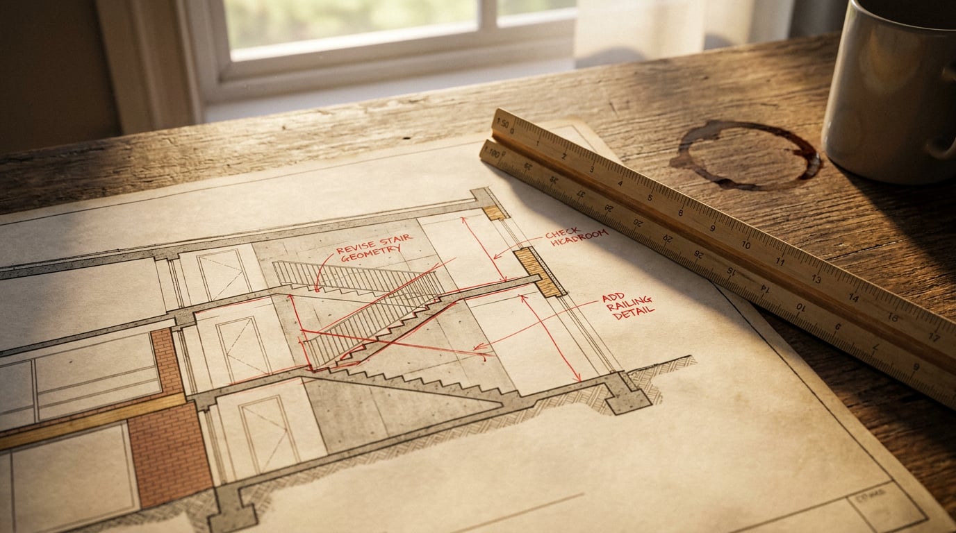
Linea BIM keeps plan and model as one building. Here is how to set up levels, types, rooms and sheets so the output reads as professional from the first issue.
Start From What Linea BIM Actually Is
 Linea is a BIM authoring tool that runs in the browser, and the single idea behind it is that the 2D plan and the 3D model are the same building, edited together. Nothing is generated from the other. Move a wall in plan and it has moved in the model; raise a roof in 3D and the plan has already caught up. That one fact changes how you set a project up, because the plan, the section and the schedule are views of one thing, not three drawings you keep in step by hand.
This article is about setup. A model that reads like a sheet is one where levels, types, rooms and tags were decided early, so that when you come to issue a drawing the sheet is mostly assembled already. The decisions in the first hour decide how painful the last day is.
### What you are modelling with
The building elements are parametric: walls, doors, windows, stairs, roofs, columns, railings, lifts, slabs, ceilings and zones. Levels stack into storeys. There is a furniture library, a material library and terrain sculpting for the site. Drawing, modelling, walking the model in first person, exporting and asking Corb a question in chat are all free and included in the plan. The paid actions are the ones that call on generation or rendering, and each of those shows its cost on the card before it runs.
### Two ways in
Know your entry route before you begin. You either model from scratch, or you import DWG, DXF or IFC and build on what already exists. A refurbishment starts from the surveyor's DWG. A new-build concept often starts from a blank site. A project that has been through another office may arrive as IFC. The choice matters because an import carries someone else's levels, units and layer habits with it, and you are inheriting those decisions.
### Where Linea sits
Linea is the BIM modelling lane of a wider suite on ArchAdemia Tools. Treat it as the source model. Sheets, renders and presentations are downstream of it, which is exactly why it pays to get the source right. A tidy model gives you a tidy perspective to send into the rendering studio and a tidy plan to drop onto a Layout board.
Because the plan and the model are one building, every setup decision you make once is inherited by every view you cut later.
Block Out in Massing, Then Switch to Build
 Linea has two workspaces over the same drawing. **Massing** is a direct-modelling toolset; **Build** is where the detailed walls, doors and windows live. The sensible order is to block out in Massing, agree the form, then switch to Build and commit to detail.
### What Massing does
Place a footprint and it lands flat, as an unextruded face. Push it into a real solid. Split faces to break a volume into parts. Drag an edge up to pitch a roof. To test an opening, Draw Rectangle on an existing face to set it out, then Extrude, which punches the opening cleanly through the solid. That gives you a fast way to try a window rhythm on a façade before any wall build-up exists to get in the way.
Group blocks so that scaffolding can be hidden without being deleted. A massing block that served its purpose can disappear from view while staying in the model, which keeps things tidy when the scheme moves on and avoids the temptation to delete something you might want back at the next client meeting.
### A concept stage example
Take a small infill site with three candidate schemes: a stepped block, a courtyard form and a single deep-plan volume. In Massing you can place three footprints, extrude each to a different height, pitch a roof on one, and group each option so only one shows at a time. That is an afternoon's work, and at the end you have three options on one site, in one model, at a consistent scale, ready to compare rather than three separate files to reconcile.
Once one option is agreed, switch to Build and develop it into proper walls and openings. The massing is the scaffolding; the Build model is the building.
### Type the numbers
Do not drag when you can type. During a gesture, start typing a number and it lands in a box beside the cursor. Press Enter to apply it, and Tab to step between values when a gesture takes more than one. Lengths read in the drawing's own units, so 6ft and 1200mm both parse. This applies across drawing walls, slabs, zones, roofs and lines, placing doors and windows, extruding a face, and the resize handles on every object. Exact dimensions typed at the moment of drawing are the cheapest accuracy you will ever buy.
Massing is for deciding the form; Build is for committing to the wall. Switch only when the massing is agreed.
Build Types and Levels Before You Draw Much
 The least glamorous part of the setup is the most valuable. Define levels and types before you draw much, because both are expensive to fix late.
### Levels first
Set your levels so storeys stack correctly. Name them properly at the start. Changing a storey height after walls, stairs and openings depend on it costs far more than getting it right in the first ten minutes. Treat the level schedule as the spine of the model: ground, first, roof, and any mezzanine or plant level, each with a sensible name that will read cleanly on a section.
### Types with real build-ups
Walls, floors, roofs and ceilings are built from types, and those types have layered build-ups. Define the build-up once and every wall of that type carries it. That is the point: you are not drawing a thick line, you are placing an element that knows what it is made of. The IFC4 export carries each type's layers, so a consultant opening your file sees the make-up of the wall and not just its outline.
For a domestic project that might mean one external wall type (cladding, cavity, insulation, blockwork, plaster), one internal partition type, one ground floor and one upper floor type. A handful of well-built types covers most of a house. A new one is better than a one-off override.
### Structure and glazing
The structural layer is covered by columns, beams, purlins and trusses, with a labelled structural grid to set them out against. Use curtain walls where a façade is a glazed system, rather than drawing panels one at a time. A glazed entrance or a shopfront stays a single editable system instead of forty separate elements.
### Colour, not texture
New geometry is born in a flat painted colour, never a texture. A new wall is white, floors and roofs are light grey, and metalwork is plain metal. A photographic finish is only ever on a surface because you painted it there. So paint a finish on deliberately where the drawing needs one, such as brick on the street elevation or timber on a soffit, rather than expecting surfaces to arrive pre-finished. Flat colour is also what keeps a plan readable.
Name the levels and define the types before you draw walls. Both are inherited by everything that follows.
Rooms, Schedules and Tags: Where the Model Starts Reading as BIM
Geometry alone is a 3D drawing. Rooms, schedules and tags are where it starts to behave as a building model. ### Rooms as you go A room carries a number, a name and an area, and each one lands as a row in the room schedule. Make that a habit as you model, not a task for the end. When you finish a floor, name the rooms on it. If you leave it, room data becomes a clean-up job, and clean-up jobs get skipped under deadline. ### Schedules that sit on sheets Schedules of rooms, doors, windows and stairs place on sheets as tables. Because they read from the model, the sheet and the schedule cannot disagree about what is in the building. Check them as you would any issued drawing, but you are checking a table drawn from the model, not one typed up separately. ### Tags Tags on doors, windows, rooms and walls make a plan legible at a glance. The rule is consistency. Tag every door or none; tag every room or none. A plan with half its doors tagged looks unfinished however good the geometry underneath, and a reviewer will read the gaps as errors. ### What the IFC4 export holds State what the export carries and no more. Rooms go out as spaces with floor area and volume. Walls and slabs carry base quantities. Each type's layers go with it. That is a useful, honest set of data to hand to a consultant, and it is worth describing exactly that way rather than overselling it. ### Drafting over the plan Real 2D drafting sits over the model. Model lines are real at the level's elevation in 3D as well; detail lines are plan-only. You have line, polyline, rectangle, circle, arc, text, leader, revision cloud and hatch, on member-named layers with their own colour, weight and linetype. Offset, trim, extend, mirror, fillet, explode and join tidy the linework. Use layers deliberately: working notes on one, hatch on another, revision clouds on a third, so each can be hidden or kept off the plot independently.Name rooms and place tags as you model. Room data left to the end rarely gets done properly.
Issue a Sheet at True Scale
A drawing reads as a drawing, not a screenshot, because of two decisions: the scale and the paper size. Everything else follows from them. ### Export at plotted scale Export a drawing sheet as a PDF at a true plotted scale on a chosen paper size, with a title block. Choose the scale because it suits the drawing, not because it makes the plan fit. A 1:100 plan on A1 and a 1:50 detail section on A3 are different documents with different jobs. Linea lets you make that choice explicitly, so the sheet that leaves the building is one a reader can measure. ### Sections and elevations from the model Cut sections and elevations from the model as real linework and issue them on a sheet like a plan. They are derived from the same building as the plan, so they cannot drift out of step with it. Save views so you can reissue them after the model moves, including a saved eye-height view captured mid-walk, which is useful for a quick sightline check at the entrance. ### Layers that stay off the sheet Use layers with hide and do-not-plot settings so working linework never reaches the issued sheet. Construction lines, setting-out notes and your own reminders belong in the model and not on the page. Set them to not plot and they cannot leak into a drawing that goes to the client or the council. ### A planning application checklist For a householder or small commercial planning submission, one model should give you all of the following:- Floor plans for every level, tagged and with rooms named.
- A section cut through the stair or the most informative part of the building.
- Elevations for each face, cut from the model.
- Schedules of rooms, doors and windows placed on sheets.
- Title blocks and a consistent scale and paper size across the set.
A sheet reads as a drawing because you chose its scale and paper size on purpose, and because every view on it came from one model.
Move Work In and Out Without Losing the Plot
Real projects do not live in one tool. Linea imports DWG, DXF and IFC, and exports DWG (with DXF as the alternative) and IFC4. The IFC import takes native files from Revit or Archicad, so a consultant's model can come in and be built on. The aim is to move work in and out without it losing its meaning on the way. ### Importing the right drawing A practice CAD file routinely holds twenty-odd drawings in one model space, all on the same layers. Ticking layers cannot pick out the one plan you want. The import dialog draws the file before it lands and finds the separate drawings inside it. Click an outlined region, or drag a box by hand, to crop the import to the single plan you want. It is cut clean at the edge and lands on the origin. Cropping first means you bring in one plan instead of the whole archive. ### Choosing DXF or DWG DXF exports carry exact colours; DWG exports use the nearest indexed colours. If the recipient will rely on your colour coding, such as a consultant who reads services by colour, send DXF. If they simply need a file their CAD package opens without fuss, DWG will do. Pick the format by what the recipient needs and not by habit. ### Onward to visuals and to Corb Send a perspective view straight into the rendering studio for a visual. Ask Corb about the drawing for free, in chat. Corb can also build or change the model on request, but that is a paid action: Corb proposes the job in a card that states the real price, and nothing is drawn until you confirm it. Keep that distinction clear when you work. Asking is free; changing the model is priced and confirmed first. ### The habit worth keeping Set up levels, types and rooms once, and every plan, section, schedule and render downstream inherits a model that holds together. That is what a model that reads like a sheet means in practice: the discipline happens at the start, and the issued drawings simply show the result. Spend the first hour on levels and types, name rooms as you draw them, and the last day before issue becomes assembly instead of repair.Keep reading.
Try ArchAdemia Tools for yourself
Draw it, model it, render it, publish it. One place, built for architects and small practices. From £19 a month, all in.