From Revit Model to Planning Elevations and Sections: A Clean Export Workflow.
Planning elevations that come out of Revit as a tangle of hidden-line debris get returned. Here is a clean route from model to submission-ready sheets.
A planning drawing set has one job: to make a proposal legible to someone who has never stood on the site and has a stack of other applications to get through. The design may be excellent. If the elevation is soft, the scale is ambiguous or the section line weights are a flat grey mush, it reads as a worse design than it is. The cleanest way to avoid that is to treat the Revit model as the master, export deliberately, and do the restyling in a vector environment rather than patching a raster screenshot.
This guide walks the route from a Revit view to a finished elevation and section set: what to fix before you export, which format to choose, how to bring it into ArchAdemia Tools' Vector studio, how to set line weights, and how to assemble and reissue the submission. It is a workflow, not a rulebook. Your local planning authority's validation requirements decide what a valid submission is, and nothing here replaces reading them.
Fix the Export Before You Export Anything
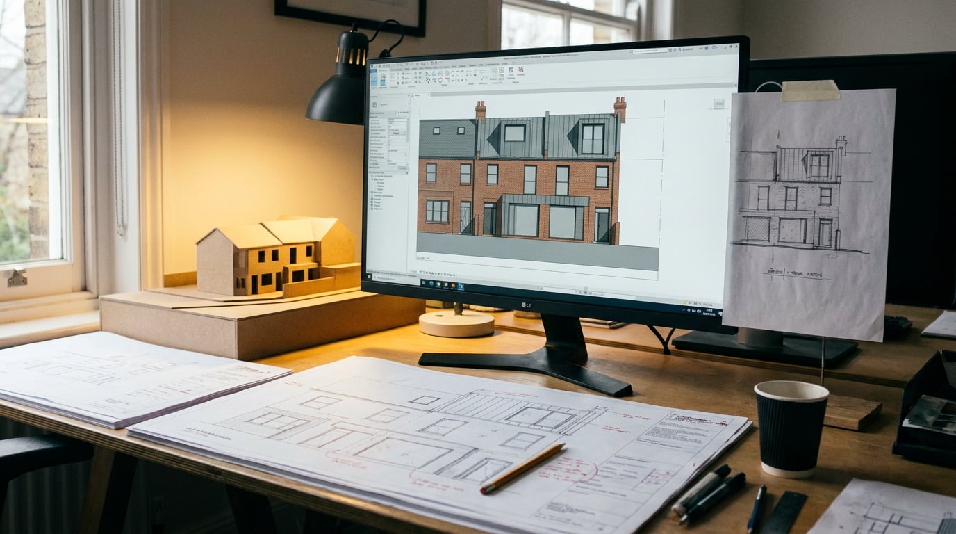
Most legibility problems on a planning sheet start in the model view, not in the export. Anything you leave wrong at source becomes repair work downstream, and repair work is where drawings quietly drift out of step with the model. So tidy the view first.
Set the view up as the sheet will read
Give every elevation and section a consistent view scale before export. If the set is going out at 1:100, make every view 1:100, rather than mixing 1:50 and 1:200 and fixing it later. Crop each region tight to the building and its immediate context. A crop box that wanders across half the site produces a drawing that is mostly empty paper, and when it lands on a sheet you will end up shrinking the building to fit the boundary.
Then strip what the reader does not need. Grids, reference planes, stray tags, scope boxes and working annotation belong in the model, not in a submission drawing. Keep levels, key dimensions and the notes the officer needs to understand the proposal, and switch the rest off in the view.
Name views for what they become
Name each view by its final role on the sheet: North Elevation, South Elevation, Section AA, Section BB. Revit's export dialogues give you control over naming, and a predictable name means a predictable file or layer set when the export lands elsewhere. "Elevation 4 - copy 2" becomes a problem the moment you have eight drawings in a folder.
Check the line hierarchy at source
Look at the line weights and linetypes in the view itself. A heavy cut line and a lighter projection line should already read as a hierarchy before the file leaves Revit. Ground line, building profile, window reveals and surface texture each want a deliberate weight. If everything is the same thickness in Revit, you can still fix it later, but you are then restyling every line by hand rather than refining a drawing that already works.
Anything you correct after export is repair. Anything you correct in the Revit view is drawing. Spend the time at source.
Decide the destination before you export
Before you export, decide what the file is for. A drawing going directly onto a planning sheet or into an upload wants a different format from one that will be re-layered, recoloured or combined with a site plan. That decision drives the next section.
Choose the Right Export: PDF, DWG or DXF
Revit exports views and sheets to PDF, DWG and DXF. In the DWG/DXF dialogue you can choose the AutoCAD file version, the naming method and whether linked files are exported as external references. Which format you pick depends on the next step, so work backwards from there.
| Format | Best for | Watch for |
|---|---|---|
| Drawings that go straight to a printed sheet, a presentation board or an upload | Linework is fixed. Restyling later means working on whatever structure the PDF carries | |
| DWG | Drawings that need re-layering, recolouring, re-weighting or combining with other CAD files | Check the version setting and test with the recipient's software |
| DXF | The same editable job as DWG when the receiving package prefers it | Confirm with whoever receives it. Compatibility is not universal by default |
When PDF is the right route
If the elevation is finished in Revit and simply needs to reach a sheet, export PDF. It is the shortest path, and a PDF exported from the model is a different thing from a screenshot or a low-resolution print. Treat that as practical guidance rather than a guarantee: check any exported PDF by zooming in hard on the linework before you rely on it. If edges break into pixels, you have exported the wrong thing, and the usual culprit is a raster route used where a print-to-PDF export should have been.
When DWG or DXF is the right route
If the drawing needs further work, export DWG or DXF and keep the layers intact. Real layers let you recolour, re-weight or hide whole categories in one move, which matters when you are building a coloured elevation for a Design and Access Statement alongside a hard-line version for the drawing set. Revit can also export rooms and areas as closed polylines, which helps if the receiving file needs area geometry.
Do not assume a particular AutoCAD version is the universal safe choice. If a consultant or a portal has a stated requirement, follow it. If not, test the file in the package that will open it before you send a full set.
Carry the scale through
Note the drawing scale at export time and carry it through. A drawing that loses its scale on the way out forces a recalibration later, and recalibration is exactly the sort of step that gets skipped on a deadline. Write the ratio down (1:100, 1:50) and confirm it on the other side.
Match the export to the next step: PDF for direct submission, DWG or DXF when linework still needs editing.
Bring the Export into Vector and Crop to the Single Drawing
Vector is the ArchAdemia Tools studio for editing the linework itself. Its front door is Import: drop in a vector-ready PDF export from Revit or AutoCAD, a DWG (AutoCAD 2000 or later, converted on the server with the upload removed afterwards) or a DXF from any CAD package, and it lands as a new document of real, editable linework. No Linea drawing is needed first.
What the import does for each format
With a PDF, Vector removes duplicate geometry, rejoins broken polylines, and offers large hatched areas as real fills you can accept or decline. Layers are restored from the PDF's own optional content groups or, failing that, by colour and lineweight. With a DWG or DXF, the file's own real layers come across as they are, and the drawing lands at true 1:1 real-world scale automatically. If the file does not declare its units, you confirm or override them. Either way the result renders for real, with fills, strokes, clip groups and text. An image inside a PDF is counted in the report and left out rather than placed.
Use the pre-import report
Before anything is created, a pre-import report shows what changed and draws the document that is about to be made. You can tick which layers to keep, so construction lines, furniture or reference geometry can be dropped before they ever reach the document.
Crop to the single drawing
This is the step that saves the most time. A practice sheet or a CAD file often holds many drawings sharing the same layers, so ticking layers cannot pick out the one elevation you want. The report finds the separate drawings in the file and outlines each on the preview. One click crops the import to just that drawing. If the detection misses it or draws the box wrongly, drag your own box on the preview and it does the same job.
Cropping dims what is outside the box rather than deleting it, cuts any linework crossing the edge cleanly, and resizes the sheet to the box. It is also the first answer to a drawing too large for the document size cap, ahead of the layer picker.
Confirm the scale before you trust it
DWG and DXF imports arrive at true scale. For a PDF, set the drawing's real-world scale from a standard metric or imperial ratio, or calibrate against a known distance. Then check it with the Measure tool: click two points for a distance, or hover a closed shape for its area and perimeter. Measure a dimension you know, such as a storey height or a door opening, before you build any annotation on top. Until a scale exists, measurements read in paper millimetres and are clearly flagged as such. Once it is set, a true scale bar regenerates whenever the scale changes.
Crop first, then calibrate, then check with Measure against a dimension you already know. Annotation built on an unchecked scale is wrong with confidence.
Tidy Linework and Set Line Weights for Planning Legibility
Planning officers read lines before they read colour. The aim of this stage is a drawing where the profile of the building, the ground, the openings and the surface detail each have a clear place in a visual hierarchy, and where that hierarchy survives reduction to A3.
Restyle in bulk, not line by line
Right-click a line and use select same to find every matching line at once, by stroke colour, stroke weight, fill or layer. Then restyle in one move. Typical decisions for an elevation:
- Ground line and cut profile: heaviest weight, so the building reads as one clear shape against its setting.
- Openings and main edges: a middle weight.
- Surface texture and projected detail: lightest weight, so brick coursing or cladding joints recede.
The ISO pen-weight presets are there so you are not typing a thickness from memory. Choose a preset for each tier and apply it to the selection.
Break up and clean stubborn linework
Imported CAD linework often needs structural tidying. The Knife makes a freehand cut across whatever it passes over, which breaks long runs into separate paths wherever you need a different weight. With nothing selected it cuts everything under the stroke, and with a selection it cuts only that. Rejoin open ends where lines should meet, use Offset Path to grow or shrink a shape's boundary by a typed distance, and use the pathfinder to clean overlapping shapes.
The Paint Bucket fills any area enclosed by the lines around it as a real new path behind the linework, with a gap tolerance so walls that stop slightly short of each other still enclose an area. It suits glazing panels, a roof plane or a tinted wall without redrawing a single boundary.
Keep colour in service of the linework
If the elevation carries tint, set the fills to Multiply in the Appearance block. The linework underneath keeps reading through the colour, which is what keeps a tinted elevation legible when it is reduced to A3. Multiply works on a path, a group or a placed image, and opacity and blend modes carry into PDF, SVG and PNG output. A DXF holds geometry and layers only, so blend modes do not travel with it.
Use the Width tool on the ground line. A Width profile such as Taper both ends makes the ground frame the elevation without overpowering the building. The profile multiplies the stroke weight, so changing the line from one weight to another keeps the taper. Like blend modes, taper exports to PDF, SVG and PNG but not DXF.
Keep the colour restrained. A planning drawing is read as linework first, and tint should support that rather than compete with it.
Select same, restyle once, and let the hierarchy do the work: heavy profile, medium openings, light surface.
Add Annotation, North Point and Title Furniture

Once the linework reads correctly, add the information that makes it a drawing rather than a picture of one.
Set type once, reuse it everywhere
Use the Type tool: click for point text, click-drag for an area frame, double-click any text to edit it. Create a named text style for levels, dimension notes and labels, and have each text item follow it, so every level tag matches without hand-matching fonts. Local overrides are available per field when one label genuinely needs to differ.
Before you share the file, use Convert to Outlines so the drawing displays correctly on a machine without your fonts installed. It is reversible: Revert to Type restores the live text if you need to edit it again.
Place furniture as SVGs
A north point, scale bar, tree symbol or practice logo goes on as an SVG. Import it with a document open and it is placed on the current sheet as its own new layer, centred and scaled down only if it would not otherwise fit. Curves stay curves, and fills, strokes, gradients, groups, clipping paths and text all come across. An SVG states a page rather than a scale, so no drawing scale is set by placing one. The drawing's own scale bar, by contrast, regenerates automatically whenever the scale changes, so a revised ratio never leaves a stale bar on the sheet.
Align with true-unit rulers and guides
Rulers run along the top and left of the drawing (Ctrl/Cmd+R) and are the only rulers in the product that read true real-world units. At 1:100, a 42mm line spans 4.2m of ruler. Drag off the top ruler for a horizontal guide, off the left for a vertical one, and use them to hold elevations and sections to a common datum and to each other. Guides snap through the same engine as everything else, save with the document and never appear in an export.
One artboard per drawing, and keep the units straight
A document holds many artboards. Give each elevation and section its own, at the correct sheet size, using the Artboards panel's presets from A4 to A0 in portrait or landscape. An A1 sheet is 841 x 594mm in landscape. Note that artboard size fields are always in paper millimetres, even when the rulers are reading metres, so an A1 sheet is 841 x 594mm whatever scale the drawing on it is at. Moving an artboard never moves the drawing, because nothing in a Vector document belongs to an artboard. That separation is what lets you resize a sheet without disturbing the drawing scale.
Export and Assemble the Submission Set
Choose the output for the recipient
Export the whole document, or one chosen artboard, as a vector PDF with real embedded fonts. When the next recipient needs editable linework, export DWG (AutoCAD 2000, written on the server, which checks its own output) or DXF as the alternative. These carry real CAD linework and editable text labels at true real-world scale once one is set, with no fills, gradients or images, which matches how CAD files are actually used. DWG and DXF have no page concept, so they always carry everything rather than one artboard.
If you need a round trip, the bridge to Linea runs both ways: Open in Vector appears on Linea's own DXF export, and Open in Linea on Vector's DXF export panel creates a new, empty Linea model ready to import it.
Assemble the set in Layout
Layout is the sheet a scheme leaves on. Bring the elevations and sections in as a Document at A3 for a Design and Access Statement, or lay them onto a single A1 Sheet for a crit board or pin-up. A multi-page PDF exports at true sheet dimensions, with optional bleed and crop marks for print. Manual layout work costs no credits, and you can also ask Corb to fill a text frame or build a document page by page, which does use credits.
Run a last checklist
- Scale stated on each drawing and confirmed with Measure against a known dimension.
- Levels labelled and consistent across elevations and sections.
- North point present where the authority expects one.
- Line weights hold when the sheet is printed at its actual size and when reduced to A3.
- File sizes sit inside the portal's upload limit.
- Fonts outlined or embedded so nothing substitutes on another machine.
Corb can answer questions about a drawing in Linea for free, but whether a submission satisfies your local planning requirements is a call for you and your planning consultant. Check the authority's published validation guidance for the specifics.
Keep the model as the master
Keep the cleaned Vector document as the working master for the drawing sheet, and keep the Revit model as the source of truth for the building. When the model moves, re-export from Revit and repeat the same import, crop and restyle. Because the line-weight decisions are already made and the select-same logic is repeatable, a revision reissues in a fraction of the time it took the first time, rather than being redrawn.
Fix the view in Revit, export the right format for the next step, crop and calibrate in Vector, set the line hierarchy once, and treat every revision as a repeat of a process you have already solved.
The route is the same whether the set is a householder extension or a mixed-use scheme: a clean model view, a deliberate export, and a vector drawing you control from there. Do it once properly and the next revision is a re-export, not a redraw.
Keep reading.


Try ArchAdemia Tools for yourself
Draw it, model it, render it, publish it. One place, built for architects and small practices. From £19 a month, all in.