From Finished Scheme to Building Control Package, Step by Step.
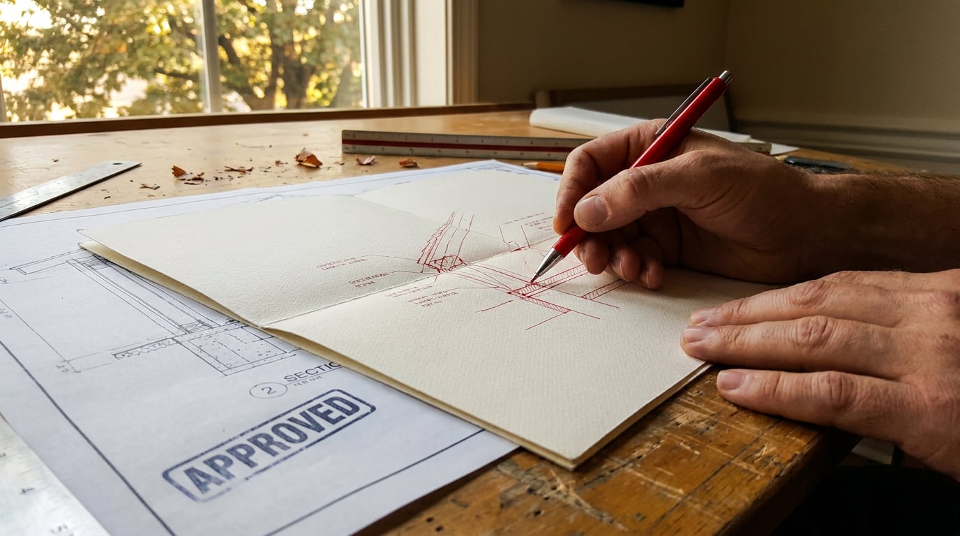
Your concept is signed off and the client is impatient. Here's how to turn a finished design into the working drawings building control actually needs.
Why a Finished Design Isn't a Finished Drawing Set
Planning drawings sell an idea. They show massing, external appearance, how the scheme sits against neighbours, and enough of the internal layout to satisfy a case officer that the accommodation works. What they almost never contain is the information building control actually needs to grant approval: structure, fire strategy, means of escape, drainage, thermal performance and accessibility, the territory covered by Approved Documents A through M in England and Wales.
The gap is bigger than most practices admit to clients. A planning set typically has no construction detail, no structural notation, no specification, and often no accurate floor-to-floor levels because nobody needed them to get consent. The wall on a planning drawing is a line. The wall building control wants to see is a build-up: masonry leaf, cavity, insulation thickness, inner leaf, U-value.
The common mistake is trying to bridge that gap by annotating the planning sheets rather than starting a proper working set. Notes get added to a drawing that was never built to carry them, dimensions get fudged to make a stair fit, and the resulting package reads as exactly what it is: a concept drawing wearing a technical drawing's clothes. Building control officers spot this immediately, and it costs more time in queries than starting clean would have cost in the first place.
This is also, structurally, a distinct stage of work. RIBA Stage 4, technical design, sits after the planning submission and before construction, and it is commonly billed separately in UK appointments. Setting that expectation with the client early, ideally at the point planning consent lands, avoids the awkward conversation later where "finish the drawings" turns out to mean "produce an entirely new set."
A planning drawing proves an idea looks right. A building control drawing proves it can be built safely. Treating the second as a light edit of the first is where most resubmission delays start.

Rebuilding the Model for Construction Accuracy
Producing building control drawings usually means moving the scheme out of a concept or massing model and into a proper construction model. In Linea, that means leaving the Massing workspace, which is exactly right for blocking out a scheme and testing footprint against the site, and moving into the Build workspace, where walls, doors, windows, stairs, roofs, columns, lifts, slabs and zones exist as parametric elements rather than pushed-and-pulled solids.
The wall is the clearest example of what changes. A massing wall is a face with no depth logic behind it. A Build workspace wall carries real thickness and a material assignment, which is what lets a thermal or fire conversation actually happen on the drawing rather than in a separate spreadsheet nobody cross-references. This mirrors how BIM authoring tools generally work: compound wall types built from multiple layers, structure, insulation, linings, each with its own material, so a U-value calculation and a fire rating can both be read directly off the same wall type.
Levels matter just as much as walls. Concept models routinely fudge floor-to-floor heights because nothing downstream depended on them being right. A structural engineer coordinating over the same building will expect accurate slab depths and structural zones, because clash detection between structure and services only works if those zones are modelled rather than guessed. Get the floor-to-floor wrong at concept stage and it can silently disappear into a section that never gets checked until the steel order is late.
Stairs, lifts and fire-rated cores deserve the same treatment. A placeholder block that reads correctly in a massing view says nothing about going width, headroom, or protected lobby depth, all of which building control and any fire strategy will interrogate directly from the drawings. Modelling these properly in Linea, rather than leaving them as dumb geometry, means the escape route analysis that follows is reading real dimensions.
If the original concept scheme lived in AutoCAD or SketchUp rather than Linea, nothing needs to be redrawn from scratch. Linea's DXF import brings CAD linework in directly, and it also reads native IFC files from Revit or ArchiCAD and GLB/FBX/OBJ/DAE/STL models, all parsed in the browser with nothing uploaded. Where a CAD file holds a dozen drawings stacked in one model space, the import dialog draws the file before it lands and lets you crop to just the plan you need, cut clean at the edge.
New geometry in Linea is born in a flat painted colour, never a texture. A wall you've just drawn is white until you assign a real material to it, which is exactly the discipline a construction model needs: nothing looks finished until it actually is.
Producing the Core Drawing Set
Once the model carries real construction information, the drawing set follows from it rather than being redrawn on top of it. Plans, sections and elevations cut directly from the Linea model come out as real linework, not a trace of a 3D view. That distinction matters at building control stage specifically, because a traced elevation loses the dimensional accuracy a plan checker will want to verify against the section.
Sheets need setting up at the scale building control actually expects: 1:50 or 1:100 for general arrangement plans and sections, dropping to 1:20 or 1:5 for the junction and construction details that follow. Linea exports a drawing sheet as a PDF at a true plotted scale on a chosen paper size, with a title block, which means the sheet leaving the model is the sheet the authority receives, not an intermediate step that gets rebuilt in another package before submission.
Real 2D drafting sits on top of the cut linework at this stage: dimension lines, hatching to distinguish construction materials, revision clouds where a sheet is being reissued after a first-round query. Linea's model lines and detail lines, held on member-named layers with their own colour, weight and linetype, are what carry this. A layer can be hidden or set not to plot, which is exactly what lets structural notation, drainage runs and fire strategy annotation live on the same base drawing without cluttering every print.
| Drawing type | Typical scale | What building control checks on it |
|---|---|---|
| General arrangement plans | 1:100 / 1:50 | Escape routes, room areas, accessibility |
| Sections | 1:50 / 1:20 | Floor-to-floor heights, structural zones, fire compartmentation |
| Construction details | 1:20 / 1:5 | Junctions, fire-stopping, thermal bridging, drainage falls |
Organising drawings on named layers pays off again here: a services engineer or building control officer asking specifically about drainage doesn't need the fire strategy layer switched on to get an answer, and the same base sheet can be issued in different configurations for different reviewers without maintaining parallel files.

Adding the Detail Drawings That Concept Sets Never Have
Building control lives or dies on the details a concept set never had reason to draw. This is where Vector earns its place in the workflow, sitting next to Linea in the dock and picking up exactly where a cut section needs annotation-heavy linework that goes beyond what a modelling tool should carry.
The route in is direct: Linea's DXF export has an "Open in Vector" action that creates a new Vector document straight from the exported drawing, so a section cut from the model doesn't need to be redrawn to gain the annotation it's about to need. Vector's Import also takes DXF files from a structural engineer or services consultant directly, landing on the file's own real layers at a true 1:1 real-world scale, which means a structural engineer's beam layout or a services consultant's drainage run can sit on the same base as the architectural section without anyone redrawing anyone else's information.
This is where junction details, fire-stopping strategy and drainage runs get drawn properly, as real vector paths carrying ISO pen-weight presets, dash patterns and hatching that reads correctly at 1:5. Vector's pathfinder tools, its live shapes, and its Width tool for tapering a stroke along its length all support the kind of detail drawing that a modelling tool isn't built for and a CAD package makes needlessly slow.
Before anything goes to print, the Measure tool checks dimensions and areas against the drawing's real-world scale, reported in true units once a scale exists, rather than trusting that a scaled-down export hasn't drifted somewhere in the process. That single check catches the kind of error, a detail printed at the wrong scale, a dimension string that doesn't match the section it annotates, that turns into a building control query if it isn't caught first.
Detail sheets belong on their own artboards within one Vector document rather than scattered across separate files. A document holds as many artboards as the set needs, each with its own name, size and position, which keeps a full set of junction details, drainage details and fire strategy annotations together as one file rather than a folder of loosely related exports that someone has to reassemble at issue time.
A detail that lives as a separate file from the section it belongs to is a detail that eventually goes out of date without anyone noticing. One Vector document, many artboards, keeps the set honest.
Assembling the Submission Package
Drawings are only part of what a local authority portal expects. The submission needs a covering narrative, a drawing index, and often a Design and Access Statement style document that ties the technical drawings back to the design intent established at planning stage. This is Layout's job, specifically its Document mode: many pages at A3, built for exactly this kind of report rather than the single large sheet a crit board needs.
Layout's Design and Access Statement template gives a starting structure, pre-populated with placeholder text and image frames, which is a faster starting point than building a report layout from a blank page every time a scheme reaches this stage. A cover sheet, a drawing index, and the supporting statement can sit in one consistent document rather than as separate Word and PDF files that need manual reconciliation before submission.
Corb, working inside Layout, can draft covering letters and compliance narrative text directly into a selected text frame, or build a new document from a prompt working from a template page by page. The writing model behind that draft is a choice, not a fixed setting: Claude Sonnet 5 or Claude Opus 5 suit a long, careful piece of compliance narrative where getting the register right matters more than speed; GPT-5.6 Sol or GPT-5.6 Terra suit a fast first draft of a covering letter; Gemini Pro is a reasonable pick where the drafting needs to sit close to other Google Workspace documents already in play on the project. None of this replaces a professional read-through before submission. A drafted compliance narrative is a draft, and the person signing the application carries the liability, not the model that wrote the first version.
Once the document is built, exporting the full package as a vector PDF at true sheet sizes gives a file that behaves correctly on a portal upload: fonts embedded, drawings at the scale they were drawn to, no rasterised text turning fuzzy when a plans officer zooms in on a dimension. Where a client or contractor needs to review the set before it goes anywhere near a portal, Layout's published share link gives a read-only, revocable view of the current document, which stays live as the document is edited rather than needing a fresh export sent by email every time a page changes.
A building control submission is a document as much as a drawing set. Keeping the cover sheet, the index and the drawings in one Layout document means the audit trail of what was submitted, when, is never reconstructed after the fact.

Handling Resubmissions Without Starting Over
Building control queries rarely arrive as a full rejection. More often it's a specific point: a stair detail needs clarifying, a drainage fall needs a level added, a fire door specification needs confirming. Handling that well means not rebuilding the submission from scratch every time.
Revision clouds and layer visibility do the heavy lifting here. Rather than reissuing an entire drawing set, a resubmission can show only what changed since the last version, with a revision cloud marking the specific area that answers the query and the drawing's layer structure keeping unrelated information switched off so the reviewer isn't re-checking things that were never in question.
Because the Linea model stays live rather than being a one-time export, a query about a section that wasn't originally drawn, or a level that needs restating, gets answered by cutting a fresh view from the model rather than redrawing by hand. This is the practical payoff of having modelled the stair properly in the first place: the model already knows the going, the rise, the headroom, so a new section through it is a cut, not a redraw.
Only the affected sheets need re-exporting. Drawing numbering and the title block stay consistent across versions, which matters more than it sounds: a building control officer working through a resubmission is cross-referencing against their own notes on the previous version, and a renumbered sheet or a shifted title block adds friction to a review that should be quick.
Logging what each resubmission addressed, directly in the Layout document rather than in a separate email chain, keeps the audit trail clear for everyone involved. A short revision history page listing what changed and why, sitting alongside the drawing index, means the client, the contractor and the authority are all reading from the same record of what's been resolved and what's still open.
The Takeaway
A finished planning scheme is a finished idea, not a finished drawing set. The distance between the two, structure, fire strategy, means of escape, drainage, thermal performance, accessibility, is real technical work, and treating it as a quick annotation pass on the planning drawings is where resubmission delays start. Rebuilding the model properly in Linea, drawing the details that concept sets never needed in Vector, and assembling the submission as one coherent document in Layout turns that gap into a workflow rather than a scramble. The building control package that results reads as what it is: a set built to prove the scheme can be built safely, not a planning set wearing a technical drawing's clothes.
Keep reading.


Try ArchAdemia Tools for yourself
Draw it, model it, render it, publish it. One place, built for architects and small practices. Plans from £29 a month, all in.