The Diagram view
The Diagram view presents a drawing as pages: a plan or a live 3D axonometric, in a style of your choosing, with labels, ready to export as a picture or as CAD.
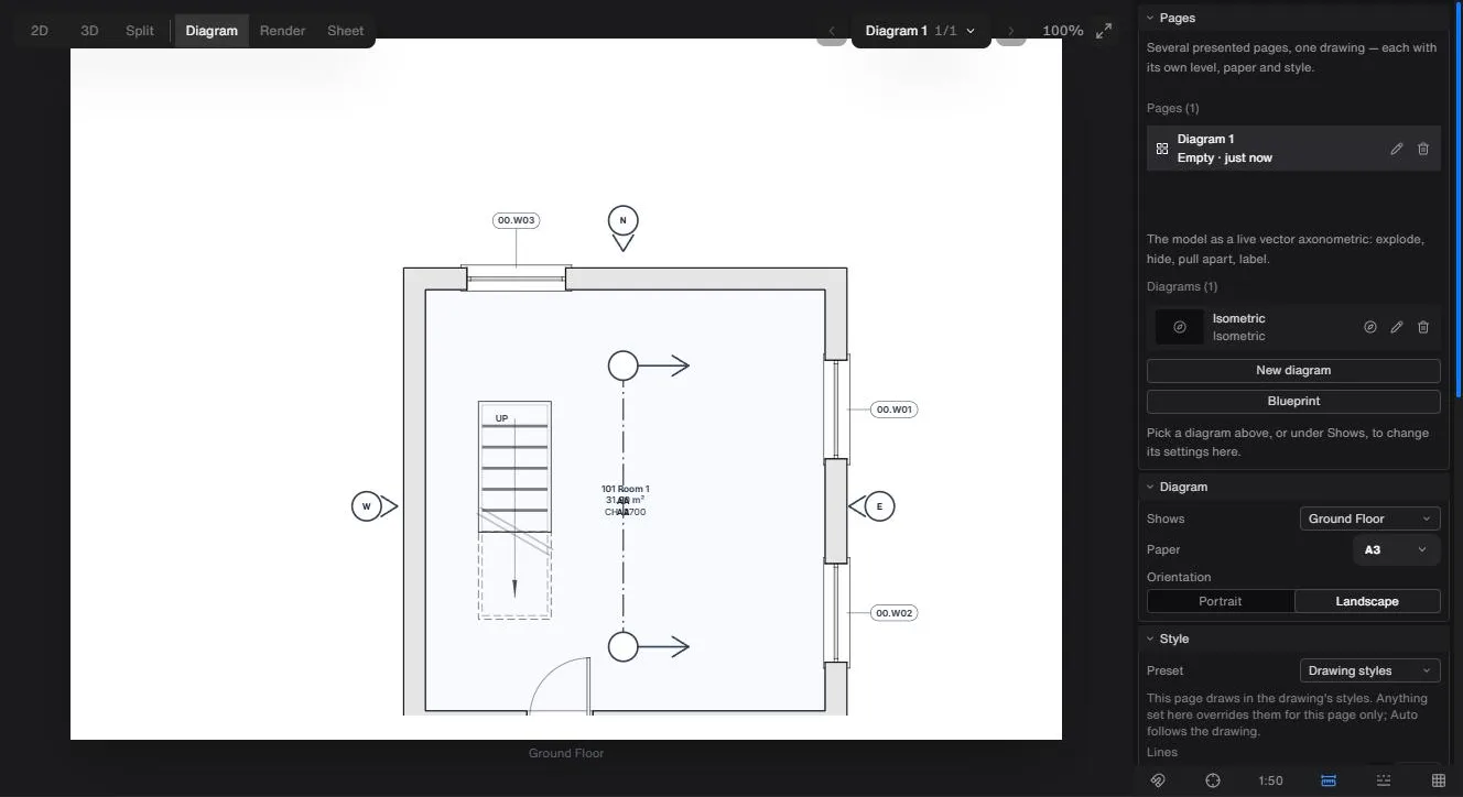
To start a diagram page
- Click Diagram in the pill at the top left. The canvas becomes a desk with a paper-sized page on it, and the tray swaps to the Diagram rows: Pages, Diagram, Style, Export and Render.
- Open the Pages chip at the top right of the stage and click Add page. The new page takes the current level and the paper, orientation and style you used last, and becomes the active page.
- In the Diagram row, choose what the page Shows: one of the drawing's levels, or a 3D diagram.
- Set the Paper size and Orientation (Portrait or Landscape).
- In the Style row, pick a Preset. The first draws in the drawing's own styles; the flat presets show Line colour, Ground and Fills, and changing one switches the page to Custom.
- Open Export when it looks right.
The Pages chip also steps through pages with its previous and next arrows, lists them from the page name, and has Fit the page. A drawing holds up to 40 pages.
The Pages row
Pages lists every page with its name, how many notes it has and when it was created. Click a row to make it the active page. The pencil renames it (Enter saves, Esc cancels) and the bin deletes it after a confirmation. A drawing opened read-only can't have its pages changed, and the row says so.
3D diagrams
The foot of the Pages row is 3D diagrams: the model as a live vector axonometric you can explode, hide, pull apart and label. New diagram and Blueprint (an exploded axonometric in blue edge ink with a soft blue shadow) each open on a page of their own (unless the drawing already has 40 pages). Each diagram in the list can be shown on the current page, have the 3D view moved to its angle, renamed or deleted. A drawing holds up to 40.
Show a diagram on the page and its settings appear below the list: Projection (Iso, Axo 45, Axo 30), Height, Levels (Stack, Exploded, Solo), Fill (None, Tone, Material), Shadows, Edge ink, Shadow colour, Walls (Cutaway, Full, Low, Ghost), Dimensions and Clip (None, Plan cut, Section). Height is greyed out on Iso, which draws every height true. Plan cut needs a level and Section needs a section marker drawn on a plan, and the control says so when they are unavailable.
- Click a part to select it, then use the bar beside it: Hide, or Move and drag to pull it apart. Parts keeps count of what is hidden and moved, lists the hidden parts with Unhide, and Reset parts puts everything back.
- Set view from 3D takes the 3D view's current angle for this diagram.
- To label, click Add label in the Diagram row (it appears when the page shows a 3D diagram), then click the picture. Drag a label's dot or its text to move it, double-click the text to edit, and press Delete to remove it. A diagram holds a limited number of labels and tells you when you reach it.
Exporting
The Export row has Export SVG, Export PDF, Export DWG, Export DXF and Export PNG, with a PNG width of Screen 1920, Print 3840 or Poster 7680. Export DWG and Export DXF are for a 3D diagram: lines come out on their layers, fills and shadows as hatches, and labels as text with leaders. A plan page's CAD files come from the Files row instead. PDF, DWG, DXF and PNG exports run one at a time, and a greyed button gives its reason.
Rendering a page
- In the Render row, click Capture page. The thumbnail appears in the row, and clicking it selects that view; the small cross removes it.
- Choose a Model (one is marked Keeps your composition).
- Add a Direction if you want one.
- Click the render button, which shows its cost before you press it. The picture follows the page's paper and orientation, and lands under Results.